There are lots of ways resolution gets spoken about in photography: the resolution of the sensor; the resolution of the lens; the resolution of the screen on which we are viewing the image; the resolution of the projector that is being used.
When you look at the literature, it becomes rather confusing: moving from a simple 1-D view of resolution, eg the number of sensor photo-sites on the camera sensor; through to resolution at a systems level, eg the convolution of sensor+lens+aperture+projection+other-stuff.
Of course, the one thing many leave out is the weakest link: us! The human eye-brain element in discussing resolution, what we might call 'photographic acuity'.
Like many, I'm aware of the limitations of my eyes, especially after a couple of macular and cataract related operations on one eye; resulting in my vision being blurred in that eye and with a different 'white balance' relative to the other eye.
I guess what I'm saying is, there is little point trying to come up with an absolute measure of resolution, when we each will perceive the final image in different ways: eg sharpness through to artistic interpretation.
Nevertheless, as I continue to develop DOFIS as THE Magic Lantern focusing tool, I felt there was a need for some form of relative appreciation of resolution: a relative figure of merit that provides feedback as we change aperture and focus.
I believe there are two main camera-centric components for us to pragmatically think about: the sensor and the lens.
The sensor's maximum resolution may, at first sight, look easy to address, after all we know the pitch or size of a sensor photo-site and can, as a reasonable approach, use two of these to give us a line pair appreciation of resolution. For instance, my 5D3 has a pitch of 6.22 microns, giving us a maximum line pair resolution of 500/6.22 = 80 lp/mm.
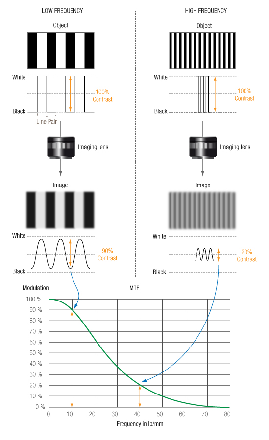
Although in this post I'm not discussing MTFs, here is a reminder of how lp/mm and Modulation Transfer Function (MTF) go together:
Before we take a more realworld look at things, let's discuss why an appreciation of image resolution is important, especially for those wishing to print their images.
Let's say, we wish to print our image on 8x10 in, good quality, photo paper. As we are capturing our image on a full frame 5D3, let’s, for convenience, say the sensor is 1in, ie let's ignore the aspect ratio. That is, a 10x magnification when we print.
Our printer says it can print at, say, 600 dots per inch as a minimum, which we will recognise as 300/25.4 = 12 lp/mm.
BTW our eyes are usually tested by using a test chart, eg a Snellen Chart or a Landolt Chart or a Tumbling E chart for those that are illiterate.
As an aside, I came across this useful insight:
"A score of 20/20 or 6/6 on a Snellen chart, or 0 logMAR score, means you can resolve details down to 1 minute of arc, which is 1/60 degree. The tangent of 1/60 degree is 0.000291, or 2.91e-4. If you are viewing a photograph from 1 m away, then the size of an object that is 1 minute of arc in size is 1000 * 0.000291 = 0.291 mm. That is the size of one line, either white or black, in a resolution, while a “line pair” requires one of each. So a line pair is twice as large, or 0.582 mm per line pair. To convert mm per line pair into line pairs per mm, just take the reciprocal: 0.582 mm per lp is 1.72 lp/mm.
An example in the other direction: Suppose you have a photograph which you know can resolve 5 lp/mm. Thus each line pair occupies 0.2 mm, and a single line is 0.1 mm. Suppose you are viewing the print from a distance of 250 mm. Then the tangent of the angle subtended at your eye is 0.1/250 = 0.0004. The arctan of that value is 0.0229 degrees, or 1.37 arc minutes. This is larger than 1 arc minute, so it corresponds to a line on the Snellen chart where the letters are 1.37 times as large as they are on the 20/20 line - approximately 20/27.5.
So if your print only resolves 5 lp/mm, and you have 20/20 vision, the print (at 250 mm) is not as sharp as your eye, and the print may not appear completely sharp. On the other hand, if the print resolves 8 lp/mm, then the minimum feature size on the print is 0.86 arc minutes, which is equivalent to a Snellen chart line of 20/17. If you have 20/20 vision, the print has more detail than your eye can see.
The logMAR score is a little more complicated, since it is the base-10 logarithm of the minimum angular resolution in arc minutes. That adds one step to the calculation."
Cutting to the chase, the minimum lp/mm resolution, on a printed image, is considered acceptable at between 5-8 lp/mm, viewing an 8x10 print at a normal viewing distance of 10in.
However, tests have been carried out that indicate some (albeit a very small number) can see a difference between an image with 15 lp/mm compared to 30 lp/mm, but not between 30 and 60 lp/mm.
Only you, the viewer will know what is acceptable, ie to you and hopefully others enjoying your art :-)
For now lets stick with 5 lp/mm, ignoring all other things, that is equivalent to 50 lp/mm on the sensor; which is OK on my 5D3, ie an 80 lp/mm sensor.
However, if we wish to print a 16x20 in image, ie a sensor to print magnification of 20, then the sensor resolution needs to be 5 lp/mm x 20, ie 100 lp/mm, but only if we continue to view the print at 10in. Most, however, would view a larger print, further back than 10in, eg at 20in. Thus if we view prints at their 'comfortable for the eye' distance, a print resolution of 5-8 lp/mm is a reasonable lower limit.
For more exacting prints, for example close scrutiny by a judge, maybe, aiming for 10-15 lp/mm seems a sensible maximum print resolution.
Of course, all the above is theoretical, as, when we take/make images in a real world, things can only get worse than the simple view presented above.
Because others (including past posts of mine) have presented the theory of diffraction, I will not be repeating that here: just using the results/conclusions.
I'm also going to ignore the 'non-diffraction optical quality of the lens', as it is near impossible to model this. I'm going to assume the lens, at all aperture values is OK, ie it's not the weakest link.
Having said that, I am going to model a lens component that degrades resolution, ie the lens aperture.
Thus, the only two things I'm going to model are the sensor and diffraction.
For the sensor, the Bayer arrangement complicates things, eg reducing the resolution of diagonal linear features:
Plus, the various filters that get used, eg low-pass; anti-aliasing; infrared, ultraviolet; etc, all contribute to 'degrading' the resolution/quality of the captured image.

However, as these are a constant, I'm going to ignore them.
As for how many sensor photosites contribute to the absolute (sensor-based) resolution, I'm going to use a simple (maximum) metric from here: https://downloads.leica-microsystems.com/Leica%20FS%20C/Newsletters/LeadingInvestigator_6.pdf

That is, you need a minimum of three photosites to address aliasing; ignoring the impact of the colour array (eg Bayer) arrangement and the various sensor filters. Thus on my 5D3, ignoring all other things, the theoretical maximum lp/mm resolution is 1000/(3*6.22) = 53 lp/mm.
Thus, if printing a 8x10 print, ie a 10x magnification, or a larger print viewed further way, the theoretical best I could achieve is 53/10, or 5 lp/mm, which should be OK when standing at the 'normal viewing distance of 10in ;-)
Note: the above ignores fancy post processing that attempts to 'sharpen things up'.
As for diffraction, I'm using the focus corrected model that is already in DOFIS, namely an MTF50 based number, based on an adjusted Dawes limit:

Where: lambda is the average wavelength in microns, ie 0.55 for a visible band sensor; N the aperture number; m the magnification at the point of focus; and p the pupil magnification.
For example, on a lens with a minimum aperture of f/4, focused at infinity, the diffraction based MTF50 lp/mm value is 172 lp/mm, ie way more than the sensor physically can resolve. In this situation the sensor limit of 53 lp/mm becomes the dominant resolution.
But at a magnification of 1, when using a macro lens, at, say, f/22, the diffraction based lp/mm value is 15 lp/mm. Clearly this now becomes the dominant resolution.
Bringing the above together, we have a pragmatically simple way of providing user feedback on resolution impacted by the sensor and diffraction:

Here we see that, until the diffraction reaches a critical value, ie the maximum sensor resolution, we will assume the sensor is the limiting element. Once diffraction gets larger than the critical value, the diffraction will drive the resolution.
As we could be mislead by the numbers, we will base the user feedback on showing the % degradation in resolution, relative to the sensor maximum, ie 1000/(3*sensor-pitch), ie with the aperture wide open and thus with negligible/low diffraction.
A refinement on the above model, and a more realistic one, is to take the sensor and diffraction in quadrature, to arrive at a ‘system’ resolution.
The latest version of DOFIS, with the above model, can be downloaded from the right.
When running you will typically see something like this:

Here we see we see we are using a 100mm lens, in fact a Canon macro lens, and that we are focused at 3.65m. The DOFIS relative and diffraction corrected DoF is 28cm in front and 33cm behind the point of focus. DOFIS is also telling us that we will need to take about 7 images if we wish to focus stack to the hyperfocal. Note the RoT hyperfocal at 25 microns is 100/10/0.25 = 40m.
We also see a green box, indicating that, at f/8, diffraction is not yet dominating things. The 100% tells us that the resolution is maxed out and dominated by the sensor.
Finally, as we don't see any macro info in the top right DOFIS area, we must be at a magnification less than 0.5 (which is what I set as my trigger point to change depth of field models).
Lets close the aperture down to f/16 and see what happens:

As we haven't changed focus we are at the same magnification as before. However, we now see a red box, indicating that diffraction is now driving things. The near and far (relative) depth of fields have increased, although, because we are in diffraction aware mode (the + sign), not by much. Nevertheless we now only need to take 5 brackets to reach the hyperfocal.
Finally we also see that, because of diffraction, our resolution has reduced to 78% of the wide open, sensor maximum.
Let's now leave things at f/16 but focus to achieve the maximum magnification:

Now we see we are focused at the minimum focus distance of 30cm and we are at a magnification of 1.0. Because we are over a magnification of 0.5, the depth of field model has switched to a one that accounts for diffraction at the macro level, ie m shown. We therefore see the depth of field, either side of the point of focus, being estimated at 1.3mm.
Finally, we see the resolution has reduced to 37% from its maximum value, ie because of diffraction.
As this has been another long post, I'll end it here.
As usual I welcome feedback on this post and, of course, DOFIS.
No comments:
Post a Comment