Anyone with a tilt shift lens knows that they take a bit of effort to use. Shifting is relatively easy and a great way to achieve panoramas, for example, this pano, of the Fairy Pools in Skye, was taken with my 24mm TS-E, using positive and negative vertical shifting.

When it comes to tilting, things get a little bit more complicated, especially if you go back to basics and try and understand the Scheimpflug principle.
Lucky others, such as Emmanuel Bigler and Harold Merklinger, have created an accessible way of modelling a tilted lens:
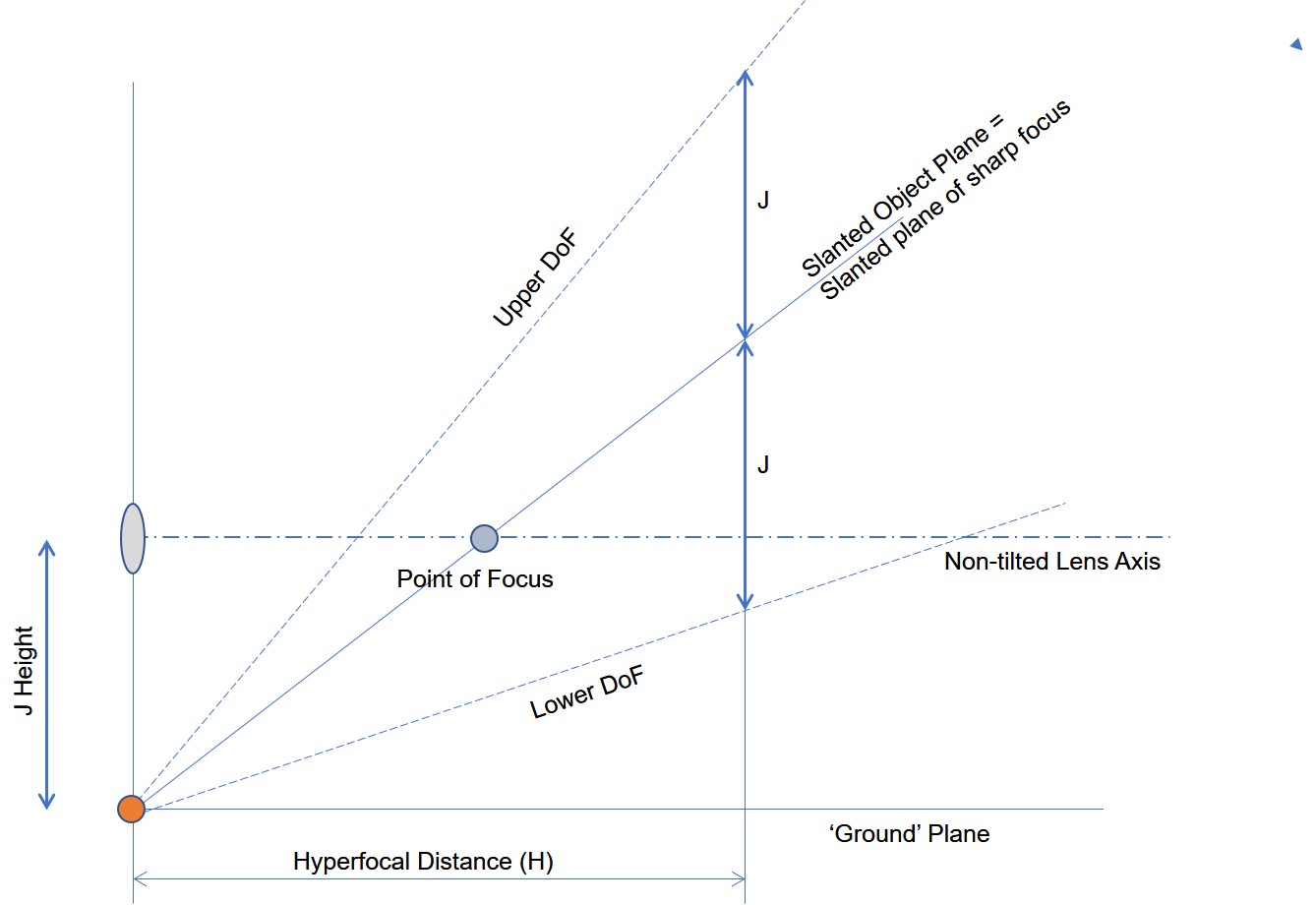
Where the J height is simply the focal length divided by the sine of the tilt angle.
To complete the model, as the hyperfocal distance is measured from the front principal plane, but Canon/ML gives us the focus distance from the sensor plane, a split thin lens model is used to calculate the TS-E 'thickness'. See http://photography.grayheron.net/2019/05/splitting-things-apart.html
As can be seen, a tilted lens has a very simple geometry that results in the angular depth of field being the J height, at the hyperfocal, ie parallel to the sensor plane.
Using the above model, it is a simple process to write a Magic Lantern Lua script to provide in-camera feedback and functionality.
The script is called Tilter and, as usual, can be downloaded from the right.
The script is positioned in the ML Focus menu and has two menu items. The first one simply switches the script on and off. The second allows the user to enter the estimated hinge angle. The menu offers 1/10 degree increments, but setting a TS-E lens to better than half to a third of a degree is about the best you will achieve.
The menu looks like this:

The Hinge or Tilt Angle, which is adjusted in 1/10 degree increments, dynamically shows the J height in cm. That is the position of the 'ground' plane, vertically below the (down tilted) lens and parallel to the non-tilted lens axis. In the above screen shot, the Hinge Angle has been entered as 7, ie 7/10 of a degree, and at a focal length of 24mm this equates to a J height of 196cm.
The script, obviously, runs in LV, and if turned on the user interface looks like this (note the camera settings are purely illustrative and note I'm handholding):

On the left we see a representation of :
- the ground plane (white horizontal line) that contains the hinge point;
- the point of focus, as projected on to the ground plane;
- the lens axis (orange) that is parallel to the ground plane;
- the depth of field wedges (upper and lower) and the plane of sharp focus, all pivot around the hinge. The plane of sharpest focus passes through the point of focus of the lens, on the (non tilted) lens axis;
- the hyperfocal distance, ie the white vertical line;
- the ground plane is projected out to three hyperfocal distances, with 2H also shown as a tick mark;
- the red dot at the (far left) centre of the display is used to provide focus stacking feedback; turning green if the current focus overlaps the last image;
- finally, 15 degree tick marks are shown for convenience.
On the right hand side of the screen, various numerical data are shown:
- The upper depth of field (U);
- The plane of maximum sharpness (F);
- The lower depth of field (L);
- The J height in cm;
- The optical, diffraction and RMS total blurs, in microns. Note the optical blur is that set on the ML DoF menu for the 'circle of confusion'.
In the above example the focus is set less than the hyperfocal and thus shows as a yellow dot, through which the plane of sharpest focus passes, ie if the dot was positioned on the lens axis. In this case the angle is estimated as 48 degrees.
In this case the upper depth of field, ie where the optical blur equals that ML set CoC, ie at an angle of 57 degrees, and the lower is at 34 degrees. The J height being 1.96m, eg the camera is on a tripod at 1.98m above the ground.
The blurs show that the ML CoC was set to 20 microns and the diffraction blur is estimated at 8 microns, giving an RMS total blur of around 21 microns.
To consolidate what is happening, let's look at another screen shot:

In this example I'm using a very high aperture (f/18, giving a diffraction blur of 24 microns). We now see that the focus point has turned green, meaning that I'm focusing between H and 3H. Beyond 3H, the focus point turns red. Focusing beyond 3H will be difficult with a 24mm TS-E, as Canon focus feedback collapses in the far field, ie relative to the near field.
The above shows the optimum configuration for tilting, where the lower depth of field covers the ground.
An additional feature of the script is that it supports tilted focus stacking. To use this, simply take an image. The next image will now be referenced to the previous and if the (slanted) depths of field positively overlap, the red dot at the centre of the circle will turn green.
In subsequent posts I'll talk about work flow and how to achieve tilted focus stacking.
As usual I welcome feedback on this post and the script.
No comments:
Post a Comment